(Hong Kong)

Product Summary
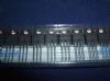
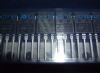
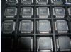
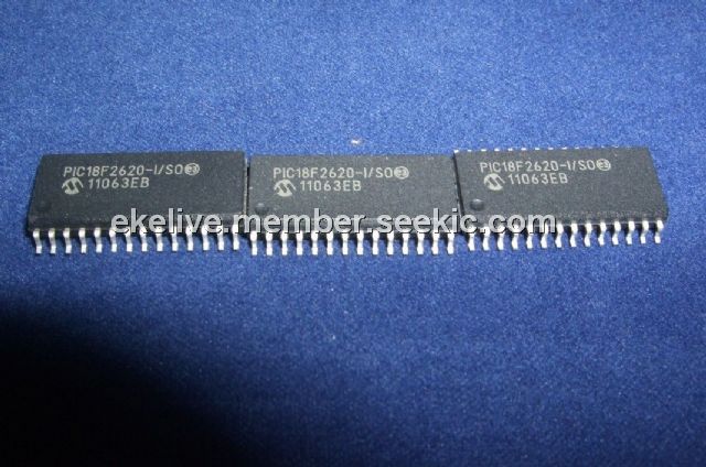
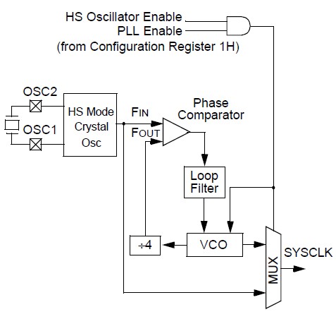
The PIC18F2620-I/SO is a 28/40/44-Pin Enhanced Flash Microcontroller with 10-Bit A/D and nanoWatt Technology. The PIC18F2620-I/SO includes an internal oscillator block which generates two different clock signals; either can be used as the microcontroller clock source. The PIC18F2620-I/SO may eliminate the need for external oscillator circuits on the OSC1 and/or OSC2 pins. The main output (INTOSC) is an 8 MHz clock source, which can be used to directly drive the device clock. It also drives a postscaler, which can provide a range of clock frequencies from 31 kHz to 4 MHz. The INTOSC output of the PIC18F2620-I/SO is enabled when a clock frequency from 125 kHz to 8 MHz is selected. The other clock source is the internal RC oscillator (INTRC), which provides a nominal 31 kHz output. INTRC is enabled if it is selected as the device clock source.
Parametrics
PIC18F2620-I/SO maximum ratings: (1)Ambient temperature under bias: -40℃ to +125℃; (2)Storage temperature: -65℃ to +150℃; (3)Voltage on any pin with respect to VSS (except VDD and MCLR): -0.3V to (VDD + 0.3V); (4)Voltage on VDD with respect to VSS: -0.3V to +7.5V; (5)Voltage on MCLR with respect to VSS: 0V to +13.25V; (6)Total power dissipation: 1.0W; (7)Maximum current out of VSS pin: 300 mA; (8)Maximum current into VDD pin: 250 mA; (9)Input clamp current, IIK (VI < 0 or VI > VDD): ±20 mA; (10)Output clamp current, IOK (VO < 0 or VO > VDD): ±20 mA; (11)Maximum output current sunk by any I/O pin: 25 mA; (12)Maximum output current sourced by any I/O pin: 25 mA; (13)Maximum current sunk by all ports: 200 mA; (14)Maximum current sourced by all ports: 200 mA.
Features
PIC18F2620-I/SO features: (1)C compiler optimized architecture: Optional extended instruction set designed to optimize re-entrant code; (2)100,000 erase/write cycle Enhanced Flash program memory typical; (3)1,000,000 erase/write cycle Data EEPROM memory typical; (4)Flash/Data EEPROM Retention: 100 years typical; (5)Self-programmable under software control; (6)Priority levels for interrupts; (7)8 x 8 Single Cycle Hardware Multiplier; (8)Extended Watchdog Timer (WDT): Programmable period from 4 ms to 131s; (9)Single-supply 5V In-Circuit Serial Programming(ICSP via two pins; (10)In-Circuit Debug (ICD) via two pins; (11)Wide operating voltage range: 2.0V to 5.5V; (12)Programmable Brown-out Reset (BOR) with software enable option.
Diagrams
| Image | Part No | Mfg | Description |  |
Pricing (USD) |
Quantity | ||||||||||||
|---|---|---|---|---|---|---|---|---|---|---|---|---|---|---|---|---|---|---|
 |
 PIC18F2620-I/SO |
Microchip Technology |
8-bit Microcontrollers (MCU) 64KB 3968 RAM 25 I/O |
Data Sheet |
|
|
||||||||||||
| Image | Part No | Mfg | Description | |
Pricing (USD) |
Quantity | ||||||||||||
 |
PIC1018SCL |
Other |
|
Data Sheet |
Negotiable |
|
||||||||||||
|
PIC10F200 |
Other |
|
Data Sheet |
Negotiable |
|
||||||||||||
|
PIC10F200-E/MC |
Microchip Technology |
8-bit Microcontrollers (MCU) 384B Flash16B RAM 4 I/O |
Data Sheet |
|
|
||||||||||||
|
PIC10F200-E/OT |
Other |
|
Data Sheet |
Negotiable |
|
||||||||||||
|
PIC10F200-E/P |
Microchip Technology |
8-bit Microcontrollers (MCU) U 579-PIC10F200-I/P |
Data Sheet |
Negotiable |
|
||||||||||||
|
PIC10F200-I/MC |
Microchip Technology |
8-bit Microcontrollers (MCU) 0.375KB Fl 16B RAM |
Data Sheet |
|
|
||||||||||||